Cards · A7 · Instrument Slot
A7 Field I/O
The field side of a controller — ±10 V and 4–20 mA, relays, counters, RS-485 and an E-stop loop.
At the fab
What it is
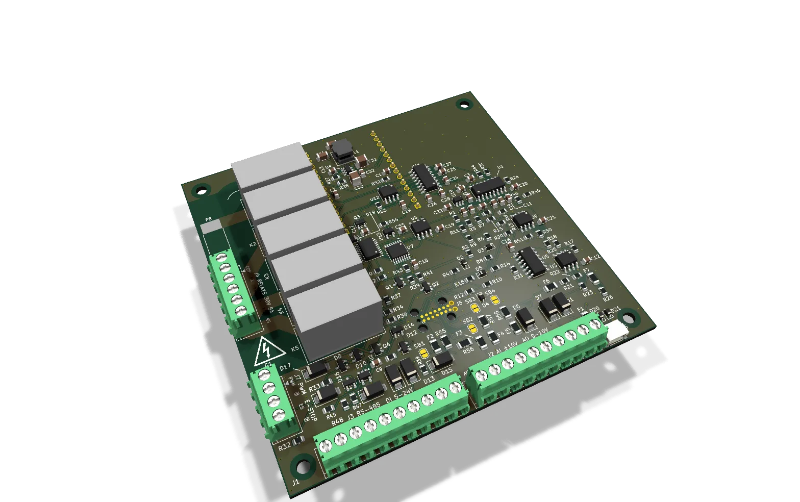
A7 is the utility card: the field side of a small process controller. It speaks the real world's language — volt-free contacts into another machine, pulse counters, ±10 V and 4–20 mA signals, a serial bus — and it runs a build with no mains anywhere in the box.
Capabilities
Design values. Measured values replace these after bring-up.
- Four ±10 V analog inputs, 12-bit. Each one becomes a calibrated 4–20 mA input by closing a solder jumper.
- Two 0–10 V analog outputs.
- Five relays, normally open, for low-voltage loads only (30 V at most).
- Four 5–24 V digital inputs, with pulse counting in Slot A.
- One 30 V, 0.5 A PWM output.
- RS-485, a Qwiic connector and +17 V sensor power.
- An E-stop loop input that stops the whole Base.
- Not isolated.
Build with it
- CNC spindle. Run contacts and a tachometer counter, into a drive that carries its own mains.
- USB-C cycle-life tester. A 24 V gearmotor and a cycle counter.
- Filament dry box. An all-24 V box.
- And the other build of every mains example: where an E1 would switch the loads, A7 and a C4 do the job through external relays and gain the counters.
Calibration
A7's analog inputs and outputs are calibrated before it ships. Its recalibration procedure will be published with the card. How calibration works
From the build log
The first four boards went to JLC
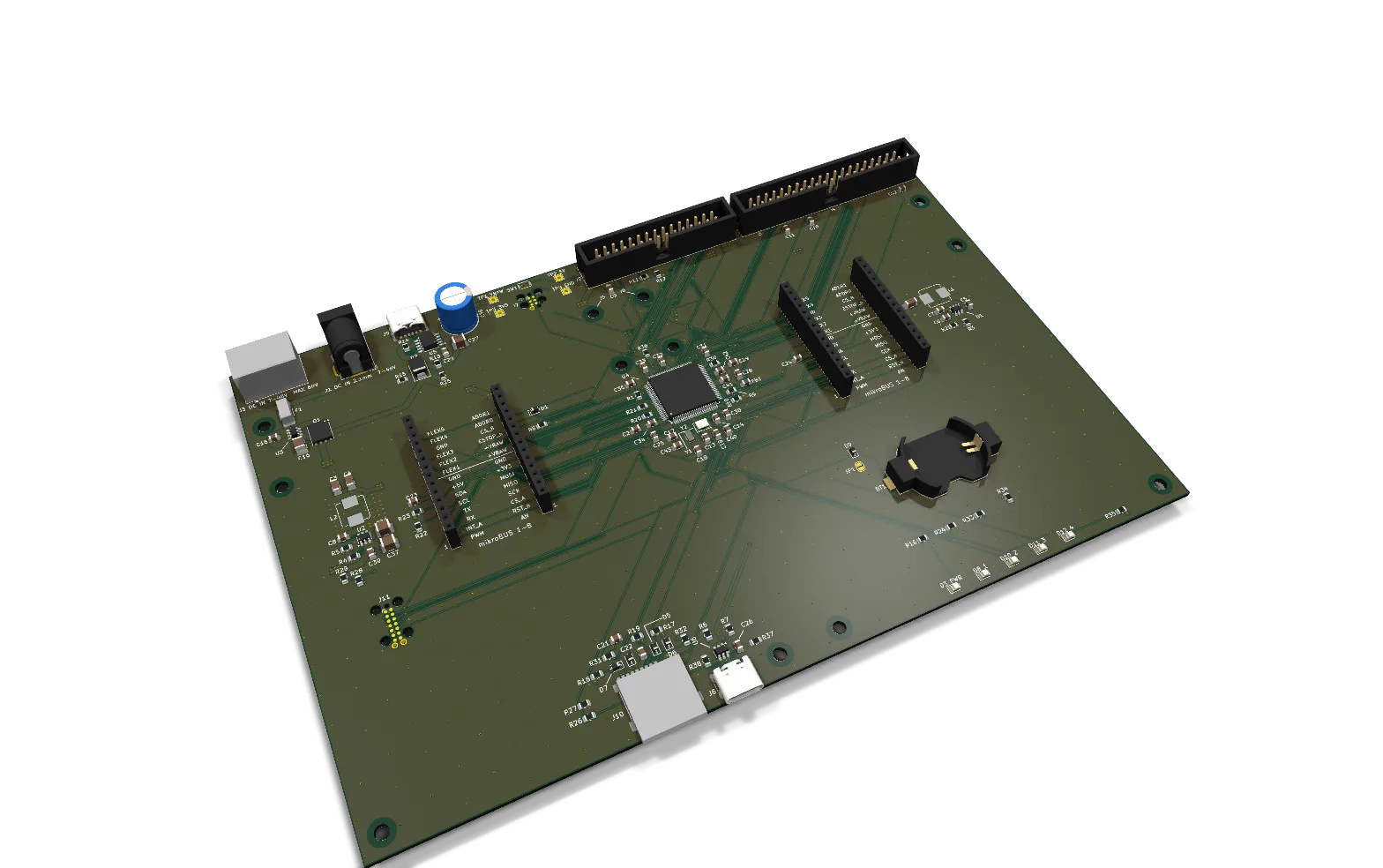
The Base, C4, B8 and A7 are at the fab, two of each. Here's what's coming back, and what happens when it does.